Simplificacion de funciones por diagramas de Karnaugh
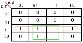
1) Pasar las
siguientes funciones a diagramas de Karnaugh (sin simplificar).
A
|
B
|
F1
|
F2BB
|
0
|
0
|
1
|
0
|
0
|
1
|
0
|
1
|
1
|
0
|
1
|
1
|
1
|
1
|
1
|
0
|
F1
F2
A
|
B
|
C
|
F1
|
F2BB
|
0
|
0
|
0
|
1
|
0
|
0
|
0
|
1
|
1
|
0
|
0
|
1
|
0
|
1
|
1
|
0
|
1
|
1
|
0
|
1
|
1
|
0
|
0
|
0
|
1
|
1
|
0
|
1
|
1
|
0
|
1
|
1
|
0
|
1
|
1
|
1
|
1
|
1
|
0
|
0
|
F1
F2
A
|
B
|
C
|
D
|
F1
|
F2
|
0
|
0
|
0
|
0
|
1
|
0
|
0
|
0
|
0
|
1
|
1
|
0
|
0
|
0
|
1
|
0
|
0
|
0
|
0
|
0
|
1
|
1
|
0
|
0
|
0
|
1
|
0
|
0
|
1
|
1
|
0
|
1
|
0
|
1
|
0
|
1
|
0
|
1
|
1
|
0
|
0
|
1
|
0
|
1
|
1
|
1
|
1
|
1
|
1
|
0
|
0
|
0
|
1
|
0
|
1
|
0
|
0
|
1
|
0
|
0
|
1
|
0
|
1
|
0
|
0
|
0
|
1
|
0
|
1
|
1
|
0
|
0
|
1
|
1
|
0
|
0
|
0
|
1
|
1
|
1
|
0
|
1
|
1
|
1
|
1
|
1
|
1
|
0
|
1
|
1
|
1
|
1
|
1
|
1
|
1
|
1
|
F1
F2
2) Para los siguientes diagramas de
karnaugh dar la funcion simlificada por los unos y por los ceros.
a)
a)
c)
1
|
0
|
0
|
1
|
d)
1
|
1
|
1
|
1
|
F(1)=1
e)
1
|
0
|
0
|
1
|
1
|
0
|
0
|
1
|
f)
1
|
1
|
1
|
1
|
0
|
1
|
1
|
0
|
G)
0
|
0
|
1
|
1
|
0
|
0
|
1
|
1
|
H)
1
|
0
|
1
|
1
|
0
|
1
|
0
|
0
|
i)
1
|
1
|
0
|
0
|
1
|
1
|
0
|
0
|
0
|
0
|
1
|
1
|
0
|
0
|
1
|
1
|
J)
1
|
0
|
0
|
1
|
0
|
1
|
1
|
0
|
0
|
1
|
1
|
0
|
1
|
0
|
0
|
1
|
3) Por un puente angosto circulan cuatro lineas
ferroviarias. Por razones de seguridad se debe impedir que circulen dosformaciones
adyacentes. Para eso se han instalado dos señales de detension. Una en la
primera y otra en la tercer via. Diseñar un circuito digital lo mas
simplificado posible capaz de encender cada una de las señales cuando la
situación lo requiera.
A
|
B
|
C
|
D
|
F1
|
F2
|
0
|
0
|
0
|
0
|
0
|
0
|
0
|
0
|
0
|
1
|
0
|
0
|
0
|
0
|
1
|
0
|
0
|
0
|
0
|
0
|
1
|
1
|
0
|
1
|
0
|
1
|
0
|
0
|
0
|
0
|
0
|
1
|
0
|
1
|
0
|
0
|
0
|
1
|
1
|
0
|
0
|
1
|
0
|
1
|
1
|
1
|
0
|
1
|
1
|
0
|
0
|
0
|
0
|
0
|
1
|
0
|
0
|
1
|
0
|
0
|
1
|
0
|
1
|
0
|
0
|
0
|
1
|
0
|
1
|
1
|
0
|
1
|
1
|
1
|
0
|
0
|
1
|
0
|
1
|
1
|
0
|
1
|
1
|
0
|
1
|
1
|
1
|
0
|
1
|
1
|
1
|
1
|
1
|
1
|
1
|
1
|
F1
F2
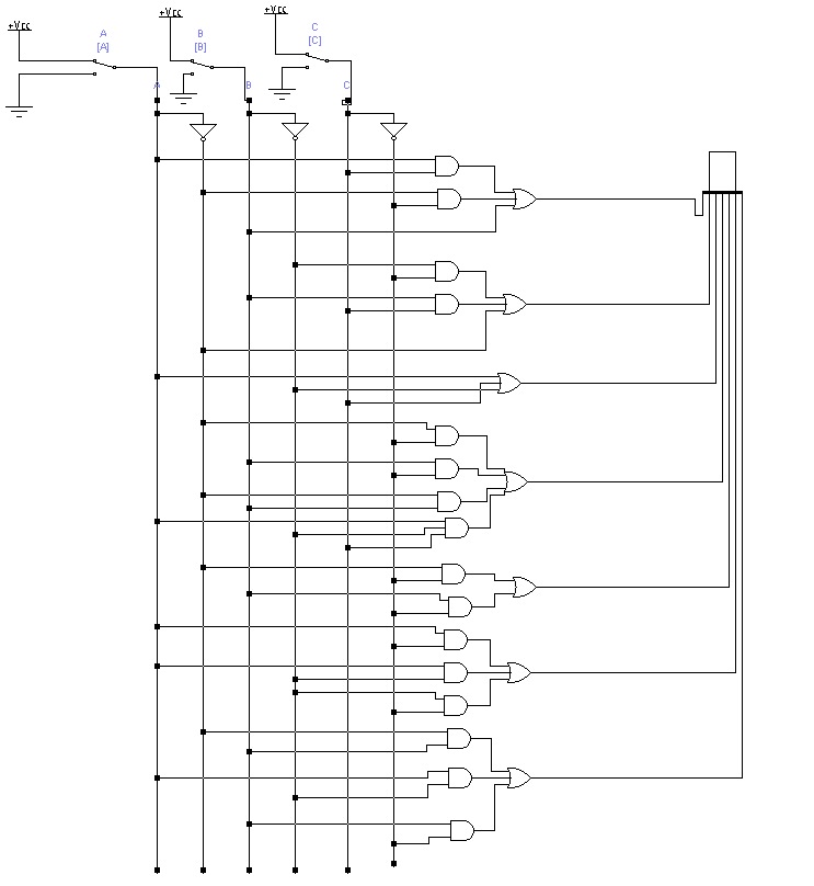
4) Diseñar un circuito digital lo mas simplificado posible
capaz de mostrar los numeros deci,ales desde el 0 al 7 mediante un display de 7
segmentos. Los numeros ingresan al circuito en binario
A
|
B
|
C
|
a
|
b
|
c
|
d
|
e
|
f
|
g
|
0
|
0
|
0
|
1
|
1
|
1
|
1
|
1
|
1
|
0
|
0
|
0
|
1
|
0
|
1
|
1
|
0
|
0
|
0
|
0
|
0
|
1
|
0
|
1
|
1
|
0
|
1
|
1
|
0
|
1
|
0
|
1
|
1
|
1
|
1
|
1
|
1
|
0
|
0
|
1
|
1
|
0
|
0
|
0
|
1
|
1
|
0
|
0
|
1
|
1
|
1
|
0
|
1
|
1
|
0
|
1
|
1
|
0
|
1
|
1
|
1
|
1
|
0
|
1
|
0
|
1
|
1
|
1
|
1
|
1
|
1
|
1
|
1
|
1
|
1
|
1
|
0
|
0
|
0
|
0
|
E)

F)
G)
5) Construir un circuito digital lo mas simplificadoposible capaz de demostrart mediante un display de 7 segmentos los numeros decimales del 0 al 9 ingresados en binario.
nota: los numeros binarios del 10 al 15 nunca estaran presentes en la entrada del circuito.
A
|
B
|
C
|
D
|
a
|
b
|
c
|
d
|
e
|
f
|
g
|
0
|
0
|
0
|
0
|
1
|
1
|
1
|
1
|
1
|
1
|
0
|
0
|
0
|
0
|
1
|
0
|
1
|
1
|
0
|
0
|
0
|
0
|
0
|
0
|
1
|
0
|
1
|
1
|
0
|
1
|
1
|
0
|
1
|
0
|
0
|
1
|
1
|
1
|
1
|
1
|
1
|
0
|
0
|
1
|
0
|
1
|
0
|
0
|
0
|
1
|
1
|
0
|
0
|
1
|
1
|
0
|
1
|
0
|
1
|
1
|
0
|
1
|
1
|
0
|
1
|
1
|
0
|
1
|
1
|
0
|
1
|
0
|
1
|
1
|
1
|
1
|
1
|
0
|
1
|
1
|
1
|
1
|
1
|
1
|
0
|
0
|
0
|
0
|
1
|
0
|
0
|
0
|
1
|
1
|
1
|
1
|
1
|
1
|
1
|
1
|
0
|
0
|
1
|
1
|
1
|
1
|
0
|
0
|
1
|
1
|
1
|
0
|
1
|
0
|
X
|
x
|
x
|
x
|
x
|
x
|
X
|
1
|
0
|
1
|
1
|
X
|
x
|
x
|
x
|
x
|
x
|
X
|
1
|
1
|
0
|
0
|
X
|
x
|
x
|
x
|
x
|
x
|
X
|
1
|
1
|
0
|
1
|
X
|
x
|
x
|
x
|
x
|
x
|
X
|
1
|
1
|
1
|
0
|
X
|
x
|
x
|
x
|
x
|
x
|
x
|
1
|
1
|
1
|
1
|
x
|
x
|
x
|
x
|
x
|
x
|
X
|
a)
1
|
0
|
X
|
1
|
0
|
1
|
X
|
1
|
1
|
1
|
X
|
X
|
1
|
1
|
x
|
X
|
b)
1
|
1
|
X
|
1
|
1
|
0
|
X
|
1
|
1
|
1
|
X
|
X
|
1
|
0
|
X
|
X
|
c)
1
|
1
|
X
|
1
|
1
|
1
|
X
|
1
|
1
|
1
|
X
|
X
|
0
|
1
|
X
|
X
|
d)
1
|
0
|
X
|
1
|
0
|
1
|
X
|
0
|
1
|
0
|
X
|
X
|
1
|
1
|
X
|
X
|
e)
1
|
0
|
X
|
1
|
0
|
0
|
X
|
0
|
0
|
0
|
X
|
X
|
1
|
1
|
X
|
X
|
f)
1
|
1
|
X
|
1
|
0
|
1
|
X
|
1
|
0
|
0
|
X
|
X
|
0
|
1
|
X
|
X
|
g)
0
|
1
|
X
|
1
|
0
|
1
|
X
|
1
|
1
|
0
|
X
|
X
|
1
|
1
|
X
|
X
|
6) Buscar y pegar la hoja de datos completa del circuito
integrado 4511 decodificador bcd a 7 segmentos de la familia cmos
7) Construir un circuito practico que permita verificar el
funcionamiento del circuito integrado 4511.Explicar la función de cada pin del
circuito
| Pin number | Name | Purpose |
|---|---|---|
| 1 | 2s | Input for the 2s bit from the binary counter |
| 2 | 4s | Input for the 4s bit from the binary counter |
| 3 | LT | Lamp test - when low, the chip takes all the segments on the display high (to test connections, etc.) |
| 4 | BI | Blanking input - when low, the chip does not output to the display - to conserve battery life, for instance |
| 5 | LE | Latch enable - latches on the current output when high (i.e. the inputs change the output when LE is low) |
| 6 | 8s | Input for the 8s bit from the binary counter |
| 7 | 1s | Input for the 1s bit from the binary counter |
| 8 | 0 V, VDD | The connection to the 0 V rail |
| 9 | E | Output for the seven-segment's E input |
| 10 | D | Output for the seven-segment's D input |
| 11 | C | Output for the seven-segment's C input |
| 12 | B | Output for the seven-segment's B input |
| 13 | A | Output for the seven-segment's A input |
| 14 | G | Output for the seven-segment's G input |
| 15 | F | Output for the seven-segment's F input |
| 16 | +9 V, VCC | The connection to the +9 V rail |


.bmp)
.bmp)
.bmp)
.bmp)
.bmp)
.bmp)
.bmp)
.bmp)
.bmp)


